Why passing IK10 test is not the same as building a reliable touch interface
In many outdoor and industrial projects, engineers often specify IK10 as a requirement for the HMI display.
However, during real deployment, failures still occur:
The glass does not shatter, but the touch stops working
The LCD breaks while the cover lens looks intact
The unit passes lab testing but fails in the field within months
This happens because IK rating is not a material strength parameter — it is a system reliability result.
This article explains IK from an engineering perspective:
not what the standard says, but what actually determines whether your HMI survives real-world impact.
1. What the IK Test Really Verifies (Most People Misunderstand This)
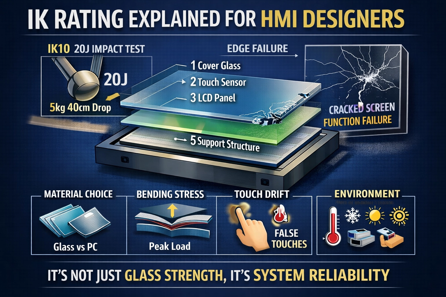
According to IEC 62262, IK10 corresponds to 20 joules impact energy, drop of 5kg object from 40cm height. But the test is not designed to prove that the glass won’t break.
The real pass criteria:
No dangerous sharp edges
No exposure of live parts
Device remains operational
Interface remains usable
In other words:
Cracks are acceptable. Unsafe failure is not.
For HMI designers, this is critical — because users don’t complain when the glass cracks.
They complain when the machine stops responding.
IK Is Not Static Strength
IK impact is a transient stress wave problem:
Millisecond impulse load
Peak stress concentration
Stress wave propagation through stack structure
Bending, not compression, causes failure
Therefore:
A glass panel that survives high pressure may still fail IK10 instantly.
How Severe is 20J in Real Life?
| IK Level | Realistic Equivalent |
| IK08 | Tool drop |
| IK09 | Strong kick |
| IK10 | Intentional strike by adult |
IK rating mainly protects the device from people, not environment.
2. Structural Design: The True Determinant of IK Performance
In practice, over 90% of IK failures originate from edge stress, not center impact.
This means thickness alone does not decide success.
Support Method (Most Critical Factor)
Impact failure is bending failure.
The same glass behaves completely differently depending on mounting:
| Mounting | Result |
| Full support | Energy distributed |
| Partial support | Edge cracking |
| Floating mounting | Instant fracture |
| Improper gasket hardness | Stress concentration |
Engineering rule:
2 mm glass with proper support can outperform 4 mm glass with poor support.
Edge Stress Concentration
Tempered glass is strongest on surface, weakest at edge.
Small edge chips → immediate catastrophic fracture
Many field failures are actually:
installation defects, not impact defects.
Internal Collision (Hidden Failure Mode)
Stack structure matters:
Cover lens / Sensor / Air gap / LCD
During impact:
Glass bends inward
Internal components collide
LCD cracks
Glass remains intact
Customers often believe “touch is weak”
but the root cause is energy reflection inside the module.
3. Material Engineering: Why Thickness Alone Is Misleading
Impact resistance relates to bending stiffness:
Impact resistance ≈ thickness³
So increasing glass from 3 mm to 4 mm is not +33%
It is a structural change.
Thermal Tempered vs Chemically Strengthened Glass
| Type | Behavior |
| Thermal tempered | Better bending resistance |
| Chemically strengthened | Better crack propagation resistance |
For IK10, crack propagation control is often more important than peak strength.
Why Polycarbonate Is Not a Universal Solution
PC has high impact resistance, but introduces long-term reliability issues:
Scratch → stress concentration → delayed fracture
UV aging → strength degradation
Thermal expansion → touch drift
Many outdoor projects eventually return to glass after maintenance problems.
4. The Real Conflict: Touch Performance vs IK Protection
In most failures, touch stops working before glass breaks.
Typical sequence:
Sensor micro-crack
ITO line fracture
Drift
False touches
Field complaint
Glass still intact
So the real IK challenge is not glass survival —
it is maintaining signal integrity.
Thick Glass Side Effects
IK10 requires thick cover lens, which causes:
Reduced SNR
Poor glove detection
Water false touches
Slow response
The solution is controller tuning and sensor design, not only stronger glass.
5. Environmental Coupling: Why Lab-Passed IK10 Still Fails Outdoors
Real failures are rarely pure impact events.
Combination conditions dominate:
Low temperature → brittleness
High temperature → reduced strength
UV aging → micro cracks
Assembly preload → sudden fracture
Therefore:IK rating is not a property of the glass — it is a property of the entire system in its environment.
6. Lab Testing vs Mass Production
Passing a drop test once does not ensure reliability.
Common production failure sources:
Torque variation during assembly
Gasket hardness tolerance
Mechanical preload
Structural deformation of enclosure
Many “impact failures” are actually stress release failures.
7. Why Engineers Specify IK10 (It’s About Cost, Not Strength)
Customers are not buying durability —
they are buying predictable maintenance cost.
| Design | Initial Cost | Service Cost |
| Standard display | Low | High |
| IK10 design | Higher | Predictable & low |
In public equipment, the true ROI is operational stability.
Conclusion
IK rating should not be treated as a glass specification.
For HMI designers, it is a system-level reliability design methodology involving:
Mechanical structure
Material behavior
Touch sensing physics
Environmental conditions
Assembly process
The goal of IK design is simple:
Not to prevent damage — but to prevent loss of function after damage.
When understood this way, IK10 stops being a checkbox
and becomes an engineering discipline.