



Learning Structural components of LCD screens is crucial whether you’re a buyer, seller, or learner:
Buyers decode cost structures and technical trade-offs better.
Salespeople deeper product knowledge and persuasive communication.
Learners get a foundational roadmap to LCD technology.
This article breaks down LCD touch screens into their two core components—liquid crystal display (LCD) modules and touch panels—explaining their layered structures and functions.
I. Liquid Crystal Display (LCD) Module: Inside-Out Structure
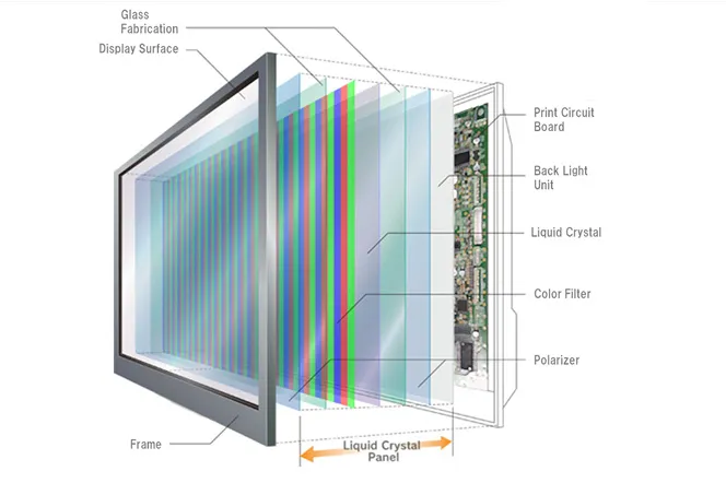
The LCD module is the core of image display, with layers progressing from the innermost to outermost:
1. LCD Panel
Core Layer: Consists of two glass substrates (Array substrate and CF color filter substrate) sandwiching a layer of liquid crystal material.
Function: Electric fields control liquid crystal molecular orientation to modulate backlight transmission, creating pixels of varying colors and brightness.
Key Attachments:
Polarizer: Bonded to both glass substrates to control light polarization, making images visible.
Spacer: Maintains uniform spacing between the two glass substrates for consistent liquid crystal distribution.
2. Backlight Unit (BLU)
Light Source Layer: Located behind the LCD panel, providing uniform illumination:
LED Beads: Point light sources arranged in arrays (edge-lit or direct-lit configurations).
Light Guide Plate (LGP): Converts point (point light) from LEDs into a uniform surface light.
Optical Films:
Diffuser: Smooths light distribution to eliminate LED hotspots.
Brightness Enhancement Film (BEF): Focuses light to increase vertical brightness.
3. Driver Circuitry
T-Con Board (Timing Control Board): Generates timing signals to coordinate panel scanning and data transmission.
PCB Circuit Board: Connects the T-Con board to external signal sources (e.g., MCUs or graphics cards) for image signal transfer.
COF/COG Packaging: Directly bonds driver ICs (Source IC and Gate IC) to the glass substrate edges, reducing bezel width.
4. Structural Support Components
Metal Frame: Secures the LCD panel and backlight module, providing mechanical stability.
Iron Mask: Covers the backlight edges to prevent light leakage and reinforce structure.
Rubber Frame: Absorbs vibration, commonly used in high-reliability automotive or industrial modules.
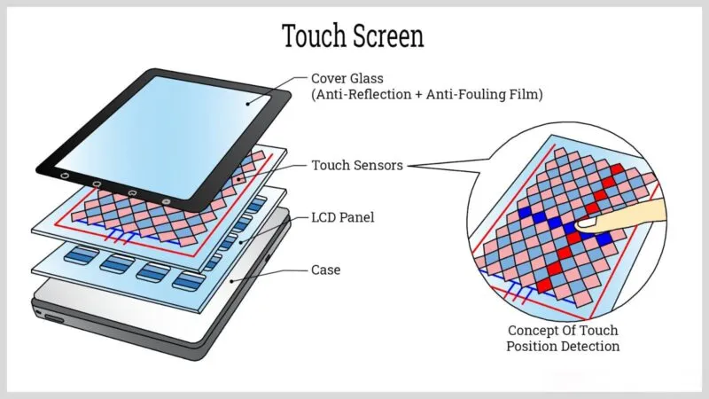
II. Touch Panel: Outside-In Structure
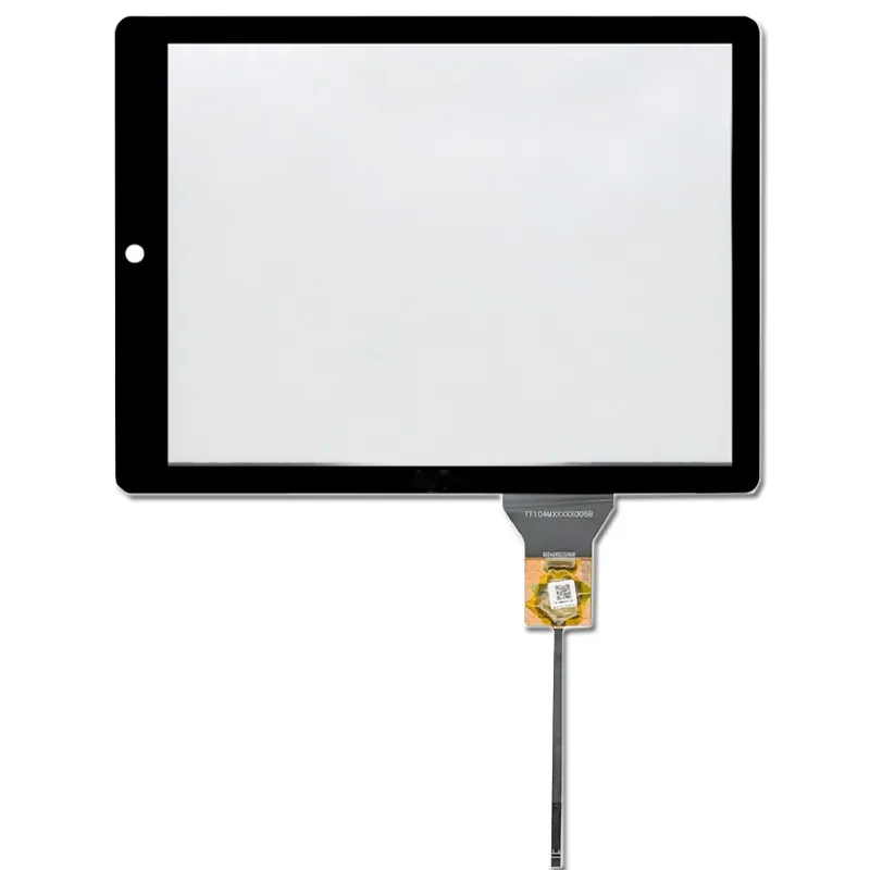
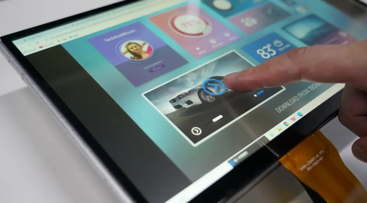
The LCD touch screens enables human-machine interaction, with layers from the contact surface inward:
1. Outer Protection Layer
Cover Glass:
Material: Tempered glass (e.g., Gorilla Glass) or acrylic (PMMA) for scratch and impact resistance.
Surface Treatments: Anti-fingerprint (AF), anti-glare (AG), or anti-reflective (AR) coatings.
Acrylic Panel: A lightweight alternative for low-cost applications.
2. Touch Sensing Layer
Capacitive Touch (Dominant Solution):
ITO Conductive Layer: Indium tin oxide (ITO) coated on glass or flexible PET substrate, forming X/Y electrode arrays.
Dielectric Layer: Insulates electrodes to prevent short circuits and detects touch positions via capacitance changes.
Resistive Touch (Less Common):
Upper PET Film + Lower Glass Substrate: Both layers have ITO coatings; touch pressure creates a conductive contact for position detection.
3. Touch Controller IC
Integrated at the touch layer’s edge or connected via FPC, it scans electrode signals, calculates touch coordinates, and transmits data via I²C/SPI interfaces to the main controller.
4. Bonding & Connection Layers
Flexible Printed Circuit (FPC): Transmits touch signals, typically with a gold finger interface.
Optical Clear Adhesive (OCA): Bonds the touch panel to the LCD module for seamless full-lamination, reducing air-gap reflection and improving light transmittance.
Air Gap (Non-Bonding): A cost-effective but lower-performance option with visible air separation, prone to dust and glare.
Key Takeaway
LCD Module Performance: Depends on precise coordination between the backlight and liquid crystal layers for brightness, color accuracy, and contrast.
Touch Panel Experience: Relies on sensing layer materials (e.g., ITO quality) and algorithms for precision, multi-touch support, and interference resistance.
By understanding these structures, can make informed decisions about products’ model selection, customization, and cost optimization.
Keywords: LCD touch screen structure, liquid crystal module, capacitive touch panel, industrial display technology
LCD Touch Assembly Integration FAQs
Do the display and touch signals share the same connector?
Check both drawings for the exact assembly. Video and touch data use separate signal paths even when the manufacturer combines some connections in one cable. Confirm each interface, supply and connector pinout against your host before wiring the sample.
Can I reuse my existing LCD and change only the touch cover or sensor?
Compare the active areas, flex locations and stack thickness. Check how the existing assembly is bonded and whether the replacement cover affects touch sensitivity or optical reflections. Send us a cross-section and the LCD model so we can review the proposed stack.
How do I isolate a touch fault from a display or backlight fault?
Check the image and backlight independently of touch input. If the image is stable, verify that the touch controller is powered and recognized by the host, then log missed touches or coordinate drift with the final cover in place. Include the symptom and assembly revision when contacting support.

