When people use LCD display devices, they are not only affected by the earth's magnetic field, but also by other devices and communication devices to a greater or lesser extent, which is also called electromagnetic interference. When these devices are working, they will become an electromagnetic source, forming a magnetic field around them and radiating electromagnetic waves outward. These devices' power determines the size of the magnetic field and the intensity of the radiation.
Analysis of LCD Display Component Characteristics and Interference Elimination Key Points
The LCD display is a pure input component, or a passive component, for the entire system. The LCD display itself has no error correction function, that is, the LCD display module can receive any signal that satisfies the operation timing relationship without the ability to judge whether it is right or wrong. Wrong signals and wrong data will generate wrong control instructions or wrong display patterns, resulting in wrong display effects. The first task of eliminating interference is to find the source of interference and the location where the interference occurs, and then use effective methods to eliminate, weaken, shield, and remedy it.
The LCD display has no display and there is no response when adjusting the contrast.
During the operation of the entire machine, electromagnetic interference affects the power line or signal line of the LCD display, generating interference pulses that reset the LCD display module. This causes the phenomenon. The result of the reset is to initialize the internal registers of the module and turn off the display at the same time. We recommend the following solution: if interference affects the power line, add a voltage stabilizing capacitor (10uF) and a filter capacitor (0.1uF or 0.01μF) between the power lines VDD and VSS closest to the LCD display module. If interference affects the signal line, we recommend adding a 0.1uF or 0.01uF filter capacitor between the signal line closest to the LCD display and VSS. We need to determine the selection of the above capacitor values according to the actual test results.
The screen produces wrong characters or random dots (data errors)
Or the screen is shifted, upside down, etc. Sometimes we cannot restore it, and we can only clear and rewrite the screen or even power on again to initialize the register for restoration. Interference applied to control signals such as the /WR signal, /RD signal, E signal, or /CS signal mostly causes this phenomenon. Interference signals are more likely to generate incorrect waveforms on these signal lines, mistakenly modifying register parameters, causing erroneous writing to display units, etc. When the entire system is operating, most programs only write data to the local display area. We recommend connecting the iron frame of the module to VSS and connecting the ground of the metal shell to VSS.
Assuming that the interference signal is applied from space to the transmission line between the MPU and the LCD display, it is recommended that:
① Use a magnetic ring or tin foil or copper foil as a shield for the transmission line;
② Change the direction of the transmission line to avoid the interference environment;
③ Shorten the length of the transmission line;
④ In the key signal line of the parallel interface mode: first add a small capacitor of 100~300pF to the ground (VSS) in the order of /WR (RD) signal or E signal, then /CS signal, and then RS signal. Serial interface mode: first add a small capacitor of 100~300pF to the ground (VSS) in the order of SCLK, then SDA, and then RSRESET.
Test and observe the improvement effect. If the interference signal comes from the system motherboard, the signal deformation can be seen from the LCD display terminal [ ]. This may be because the transmission line resistance between the MPU and the LCD display module is relatively large, and the interface driving ability of the MPU system is relatively weak, which makes it easy for the interference signal to invade. At this time, you can consider: ① Connect a small resistor in series on the transmission line to form a low-pass filter circuit with the input capacitor of the LCD display module end [ ] to eliminate the influence of interference; ② Add a transmission line driver to the system motherboard to improve the driving ability; ③ Use Schmitt circuit to shape the signal, etc.
There is no interference source, but there will be no display or chaotic LCD display
This situation is also classified as interference, but it is an internal interference of the system, mainly due to software program conflicts.At this time, we should first consider the interrupt program. When the MPU writes to the LCD display in /0 addressing mode, system operation interruptions may modify the control signal status of the LCD display module or the data to be written, causing the module to experience setting errors, crashes, or display errors. The improvement method is to turn off the interrupt response function when the MPU calls the LCD display driver subroutine.
The interference point cannot be found or the circuit preventive measures cannot be taken, but the influence of interference cannot be eliminated.
At this time, software remediation solutions need to be considered. The simplest method is to initialize the registers regularly. First, do not use the RESET signal to reset, only rewrite the registers. Because the reset action will cause the normal display to flicker, and the display effect is not very good. If a freeze occurs and we cannot recover from it, we can only use the RESET signal to force a reset and then initialize the registers.We recommend reading the "status word" of the LCD display module as the basis for initialization to ensure the normal display is not disturbed by initialization and repair interference effects in the shortest time. When we judge that the module is running in the "off display" state, we consider that interference has caused the module to stop displaying. Therefore, we call the initialization function to restart the module and turn on the display. If the module is still in the "off display" state after initialization, it is necessary to use the RESET signal to force reset and initialize. When we judge the module to be in the "on display" state, we write a set of special data to several units of the display SRAM and then read them back in turn to determine their correctness. If we detect an error, we should consider the module interfered with, then call the initialization function and refresh the data again.
Static electricity causes the LCD display module to have no display or display randomly:
This is a common interference phenomenon. The interference pulse directly passes through the LCD display screen's iron frame to affect the module's circuit.Usually, we do not want the iron frame of the LCD display module to float and become a static charge accumulation surface, so we connect it to VSS. However, such a connection makes it easy for external interference to directly affect the VSS line through the iron frame.
There are three ways to connect the iron frame:
① Use an insulating pad to isolate the module iron frame from the metal panel of the system. The thicker the insulating pad, the greater the reduction of static electricity.
② We connect the iron frame of the LCD module to the metal shell, and connect the metal shell to the ground. At this time, it may be necessary to disconnect the iron frame from the VSS in the module.
③ We connect the iron frame of the module to VSS and connect the ground of the metal shell to VSS.
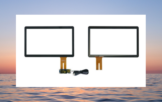
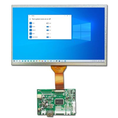
We need to test these three connection methods related to the system chassis structure and ground processing in practice to select the appropriate method. If you want to order [Industrial Display Touch Screen], you can contact us at any time, and we can customize it for you professionally.