Lcd interfaces include MCU, RGB, SPI, MIPI, LVDS, and eDP. But how much do you really understand them? For sales people or purchasers, knowing which motherboard and interface are needed may suffice, leaving the technical details to engineers. However If you’re a budding LCD technician, this article can help. we’ll first analyze pinout definitions, then discuss how different interfaces are used across various sizes, resolutions, and scenarios.
1). Core Methods to Identify Interface Types via Pinout Definitions
1. SPI Interface (Typical Pinout: 4–7 pins)
Key Pins: SCK (Clock), MOSI (Master Out Slave In), MISO (Master In Slave Out), CS (Chip Select), with possible DC power (3.3V) and GND.
Identification Features: Extremely few pins (≤7), no differential pairs, clear clock (SCK) and chip select (CS) lines, supporting unidirectional or bidirectional data transfer.
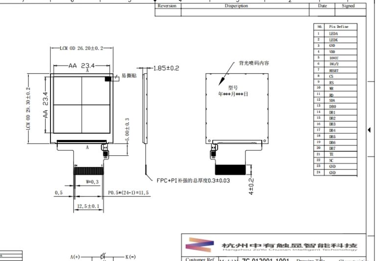
2. MCU Interface (Parallel, Typical Pinout: 20–50 pins)
Key Pins: 8/16/24-bit data lines (D0–D7/D15/D23), HSYNC (Horizontal Sync), VSYNC (Vertical Sync), CLK (Clock), EN (Enable), DC power (3.3V/5V), GND.
Identification Features: Multiple data lines (multiples of 8), no differential pairs, independent sync signals, densely arranged pins (e.g., FPC interface).
3. RGB Interface (Parallel, Typical Pinout: 20–30 pins)
Key Pins: R0–R7 (Red), G0–G7 (Green), B0–B7 (Blue), HSYNC, VSYNC, DE (Data Enable), CLK (Pixel Clock), power/GND.
Identification Features: Data lines grouped into R/G/B trios (8 pins each), clear sync signals, no differential pairs, ≥20 pins, common in industrial FPC interfaces.
4. LVDS Interface (Differential Serial, Typical Pinout: 10–16 pins)
Key Pins: 4 pairs of data differential lines (Data0±, Data1±, Data2±, Data3±), 1 pair of clock differential lines (Clock±), with possible 3.3V power and GND.
Identification Features: Multiple differential pairs (typically 4 data + 1 clock), each pair labeled “+”/“-”, 10–16 pins, common in 20-pin FPC for laptop screens.
5. MIPI Interface (Differential Serial, Typical Pinout: 10–20 pins)
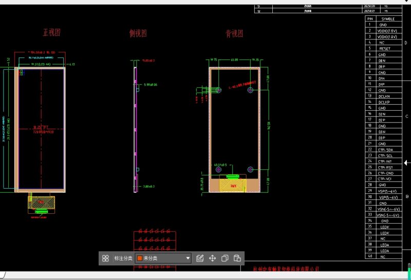
Key Pins: 1–4 pairs of data differential lines (Lane0±–Lane3±), 1 pair of clock differential lines (Clock±), AUX channels (I2C/SPI for initialization), power/GND.
Identification Features: 1–4 data differential pairs + 1 clock pair; 10–20 pins, compact interface (e.g., 15-pin FPC for smartphone screens), with pins for I2C configuration (AUX).
6. eDP Interface (Differential Serial, Typical Pinout: 20–30 pins)
Key Pins: 2–4 high-speed differential channels (Channel0±–Channel3±), AUX channel (I2C for DP protocol handshake), HPD (Hot Plug Detect), embedded clock in channels, power/GND.
Identification Features: 2–4 high-speed differential channels (e.g., 4 channels in eDP 1.4), independent AUX channel (I2C), 20–30 pins, common in 30-pin FPC for laptops/displays, with HPD support.
2). Application Scenarios of Interfaces Across Sizes and Resolutions
1. Small Displays (<3 inches, resolution ≤480×480)
SPI Interface
Size: 0.96–2.4 inches
Resolution: 128×64, 160×128, 240×240
Scenarios: Wearables, small home appliance displays (e.g., microwave panels), simple industrial indicators
Rationale: Low bandwidth (<20Mbps), but minimal pins (4–7), simple hardware design, and extremely low cost.
MCU Interface (Parallel)
Size: 1.5–3 inches (e.g., smart door lock screens, small handheld devices)
Resolution: 240×320 (QVGA), 320×240
Scenarios: Children’s toy screens, simple POS machines, small instruments
Rationale: Faster parallel transmission (10Mbps class) supports slightly higher resolution, with simple interface protocols (similar to GPIO control).
2. Medium Displays (3–10 inches, resolution ≤2K)
RGB Interface
Size: 3.5–7 inches (industrial control screens, legacy car central controls)
Resolution: 480×800 (WVGA), 720×1280 (HD)
Scenarios: Industrial HMIs, early car navigation screens, some digital photo frames
Rationale: Parallel RGB transmission offers strong hardware compatibility and simple protocols, but requires many pins (≥20) and has poor anti-interference, unsuitable for high resolutions.
LVDS Interface
Size: 7–15.6 inches (car central controls)
Resolution: 1366×768 (HD+), 1920×1080 (FHD)
Scenarios: Traditional monitors below 1080P, some car central controls
Rationale: Differential transmission resists interference, supports 1080P@60Hz, low cable cost; once the mainstream for laptop screens (gradually replaced by eDP).
MIPI Interface
Size: 5–10 inches (new car central controls)
Resolution: 1080×2340 (FHD+), 1440×3200 (2K)
Scenarios: New energy vehicle central controls, high-end handheld devices
Rationale: Serial differential transmission with few pins (<4 pairs), supports high speeds (D-PHY v2.1 up to 28Gbps), adapts to thin embedded designs, and enables 4K via compression (e.g., DSI-2).
3. Large Displays (>10 inches, resolution ≥2K)
eDP Interface
Size: 13–32 inches (high-end laptops, monitors)
Resolution: 2560×1440 (2K), 3840×2160 (4K), 7680×4320 (8K)
Scenarios: 4K laptop screens (e.g., MacBook Pro), 4K/8K monitors, high-end car multi-screen systems (e.g., Tesla Model S)
Rationale: Based on DisplayPort protocol, high bandwidth (eDP 2.0 up to 59.7Gbps), supports high resolution + refresh rates, embedded design fits motherboard integration, and resists interference.
MIPI Interface (Extended Application)
Size: 10–15 inches (some car multi-screen systems, special embedded devices)
Resolution: 2K (requires multi-lane configuration, e.g., 4-lane D-PHY)
Scenarios: Multi-screen car systems (e.g., Mercedes Hyperscreen), industrial tablets
Rationale: Increases bandwidth by adding data lanes (e.g., 4 lanes), supports 2K resolution while maintaining a compact interface.
3). Selection and Identification Summary
Selection Logic by Scenario:
Small low-res displays (wearables) → SPI/MCU
Medium industrial displays (anti-interference needed) → LVDS
Mobile devices (thin designs) → MIPI
High-res large displays (4K/8K) → eDP
Legacy medium displays (e.g., 1080P laptops) → LVDS (gradually replaced by eDP)
Key Pinout Identification Points:
Differential pairs: Pins labeled “±” indicate LVDS/MIPI/eDP.
Data line count: Parallel interfaces (MCU/RGB) have many data lines (8/16/24-bit), while serial interfaces (SPI/MIPI/eDP) have few (relying on high speed).
Clock lines: SPI/MCU/RGB have independent clock lines; MIPI/eDP embed clocks in differential channels.
Control signals: MCU/RGB use HSYNC/VSYNC; MIPI/eDP use AUX channels (I2C) for configuration.
Through these dimensions, interface types can be quickly identified, and their application scenarios understood. In practice, refer to pinout documentation and use an oscilloscope (e.g., to measure differential waveforms) for further verification.