The problem is rarely voltage — it is system disturbance
A common situation in HMI projects:
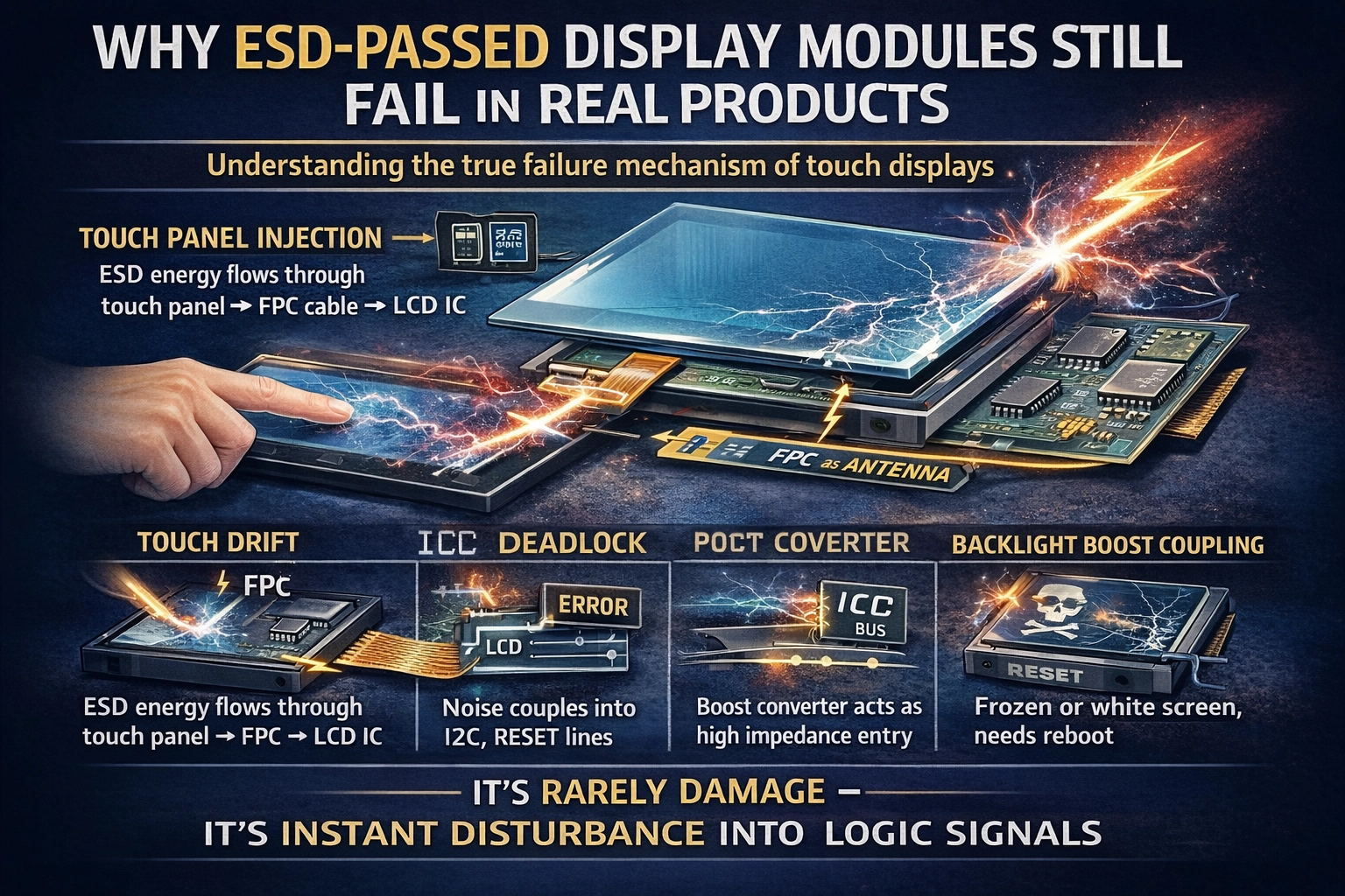
The display module passes ±8kV contact discharge in the lab.
But after integration into the final device:
Random white screen
Touch drifting
I2C locked
Device reboot
Works again after power cycle
The display is not damaged.
Yet the product is unreliable.
This is because most ESD issues in real products are not destructive failures, but functional disturbances.
ESD in modern electronics behaves more like electromagnetic interference than electrical overstress.
To understand why this happens, we need to look at how ESD actually enters a display system.
1. What ESD Really Does to a Display (Soft Failure Mechanism)
More than 80% of field complaints belong to soft failure.
| Symptom | What actually happened |
| White screen | LCD reset triggered |
| Frozen image | Communication halted |
| Random touch | Baseline capacitance shift |
| Needs reboot | Bus lockup |
| Recovers after seconds | Register corruption |
No component exceeded its absolute maximum rating.
The logic simply entered an invalid state.
2. The Real Entry Paths of ESD Energy
ESD does not damage where it strikes.
It damages where the system is weakest.
Path 1: Through the Touch Panel (Most Common)
Finger → cover glass → sensor → FPC → touch IC
Result:
Sudden capacitance spike
Interrupt storm
MCU overload
Observed behavior: ghost touches, cursor jumping
The display is electrically healthy —
but logically overwhelmed.
Path 2: FPC as an Antenna (Classic Field Failure)
An ESD pulse is a wideband RF event.
The flex cable length easily becomes an efficient antenna.
Noise couples into:
RESET
INT
I2C lines
TE signal
Result:
Communication deadlock
Typical symptom: unplug power to recover
Path 3: Power Rail Coupling
Discharge → chassis → ground bounce → voltage dip
Causes:
PMIC mis-trigger
LCD internal state machine error
temporary black screen
Nothing is damaged, but system state is lost.
Path 4: Backlight Boost Circuit Injection
The LED boost converter is a high-impedance energy entry point.
Effects:
brightness flash
flicker
temporary shutdown
3. Why Passing IEC 61000-4-2 in Lab Is Not Enough
Lab tests verify the module in isolation.
Real products introduce:
| Integration Factor | Impact |
| Plastic enclosure | Energy flows into signal lines |
| Metal grounded housing | Energy safely dissipates |
| Long FPC | Increased coupling |
| Weak pull-ups | Bus lockup risk |
| Floating ground | System reset |
Therefore:
ESD robustness is a property of the system, not the module alone.
4. Why Adding TVS Often Doesn’t Solve It
Many designs add protection diodes but still fail.
Because TVS works for:
High-voltage destructive events
But most display failures are caused by:
common-mode disturbance
ground shift
timing corruption
The IC survives — the communication does not.
5. The Correct Design Philosophy
The goal is not to “block static electricity”
The goal is to:
prevent disturbance from reaching logic states
Reliable designs follow three principles:
Provide a Discharge Path
Give ESD a preferred route to chassis ground before signal lines.
Reduce Coupling Efficiency
Shorter FPC
reference ground
shield return paths
Improve System Recovery
Watchdog
communication timeout
controller re-initialization
6. What Integrators Actually Expect From a Display Supplier
Professional customers are not only asking:
“Does it survive ±8kV?”
They are asking:
Where will it fail?
Will communication recover automatically?
Does touch remain stable during discharge?
A reliable module is not the one that never experiences disturbance,
but the one that remains functional after disturbance.
Conclusion
Most ESD problems in HMI systems are not caused by insufficient voltage tolerance.
They are caused by disturbance entering control signals before protection circuits can react.
A display passes ESD when it survives the test.
A product passes ESD when the user never notices the test happened.
Understanding this difference is the key to building stable outdoor and industrial interfaces.